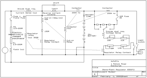
The Stone's regulator is paired up with a Stone's dynamo. These are generally higher current machines rated at 120 or 180 amps. The dynamo differs from the Wolverton style in that the negative end of field and armature windings are commoned rather than the positive end.

Regulation is achieved by electromagnetic compression of a carbon pile variable resistor in series with
the field coil. This resistor can vary over the range 5 to 400 ohms.
The following text is taken from a BR handbook explaining the operation of the Stone's System
SINGLE BATTERY TRAIN LIGHTING SYSTEM
INCORPORATING
Control Panel Type S.300/T2 or S.80/T2
THE PRINCIPAL COMPONENTS EMPLOYED IN THIS SYSTEM ARE
- "TONUM'' GENERATOR SUITABLE FOR EXTERNAL REGULATION.
- 'TONUM'' GENERATOR CONTROL PANEL, UPON WHICH ARE MOUNTED :
- Dual (current and Voltage) Generator Regulator.
- Series Coil Diverter for generator output.
- Voltage adjusters for battery and lamps.
- Automatic Cut-in Relay.
- Cut-in Contactor.
- Regulator Relay.
- Battery lsolating Link.
- LAMP RESISTANCE.
- MOTORING TERMINAL AND RESISTANCE UNIT.
- SINGLE BATTERY OF ACCUMULATORS.
- LAMPS, SWITCHES, FITTINGS, FUSES, etc.
DISTINCTIVE FEATURES
The system, entirely automatic in operation, is well adapted to meet the most widely varying conditions of train lighting service.
The regulator is designed to provide complete automatic control of the generator at all speeds above that at which full output is obtained, giving initial CONSTANT CURRENT until the battery or batteries are nearly fully charged, and ultimate CONSTANT VOLTAGE to ensure the ideal tapering charge. By this means, rapid battery reconditioning is obtained and overcharging prevented.
The Lamps and all parts of the equipment are fully protected in the event of accidental break in the battery circuit ; in such circumstances the regulator will immediately take charge of the generator, which will then run CONSTANT VOLTAGE throughout its speed range.
LAMP VOLTAGE CONTROL
The limitation of voltage at the battery terminals, imposed by the regulator, greatly facilitates lamp voltage regulation. The high charging voltage which may occur in other systems is positively precluded in this, and the final voltage to be corrected is small enough to permit an abbreviated form of lamp resistance to be used, even with extensive switching of individual lamps.
SEQUENCE OF OPERATION
When the generator is at rest, both Cut-in (UR) and Regulator (UM) Relays are in the open position and the main contactor in the "OFF'' position. The Generator is disconnected from the battery ; under these conditions the lamp resistance is short-circuited so that the lighting current may be taken direct from the battery.
When the train accelerates and the generator has developed the required Cut-in voltage the Cut-in (UR) Relay operates, closing its contacts thereby operating the Cut-in comtactor (U300). Under these conditions the Generator is connected to the battery, the lighting load being taken through the lamp resistance.
lt wilI be observed that the Regulator Voltage Coil (MJ1) is connected to the battery side of the Cut-in. Therefore the Regulator is not attempting to control the Generator voltage prior to cut-in, although the Regulation Carbon Pile is connected in the field circuit.
lf the lights are of "OFF'' the Regulator Voltage coil is connected to the battery when the generator voltage reaches a low value, by operation of the in Regulator Relay (UM) (REL).
When the lights are "ON'' the regulator voltage coil (MJ1) is always connected to the battery.
It follows from this arrangement that with a battery of average standing voltage the Carbon Pile is fully compressed before cut-in, irrespective of the cut-in voltage. Further, if the battery is just off charge and standing at a high voltage, and the Regulator operating at less than this value, the Regulator pile will be fully open, and prevent cut-in until the battery voltage has fallen to the Regulator setting.
When the train slows down, and the generator voltage falls below that of the battery, the Cut-in Relay opens by virtue of a normal series coil. Hence the Cut-in Contactor opens, disconnecting the generator from the battery and cutting out the lamp resistance so that lighting current is obtained direct from the battery.
It will be seen from the connection diagram that the lamp switch is provided with auxiliary contacts whereby part of the resistance in series with the shunt coil of the regulator is short-circuited when the lamps are "ON". The effect of this is to cause the regulator to operate at a rather lower voltage. The generator voltage, however, is raised with increase of lamp load to a degree depending on the lamp resistance drop and the selected tapping point of the Voltage Dividing Resistance (VR), except when position 4 of resistance (VDR) is chosen. At the same time the Iamp voltage will fall with increase in lamp load except where position 1 of resistance (VDR) is chosen. The most popular setting of resistance (VDR) is position 2.
With a discharged battery, the regulator operates at constant current corresponding to the full load rating of the generator. This current value is constant whether lamps are '"ON" or "OFF" so that with lamps "ON" the entire generator output, less the lamp Ioad, is available for charging the fbattery. This is a very valuable feature of the dual regulator system as it ensures the generator capacity being utilised in the most advantageous manner.
The Regulators described in this publication are of the dual operating type in which independent magnet systems impose initially constant current and ultimately constant voltage upon shunt wound Train Lighting Generators, and should not be confused with Regulators having single magnet systems and Compound Windings, which can only provide progressively falling current with rising battery voltage.