SWINDON ENGINEERING SOCIETY (B.R.,W.R) TRANSACTIONS, 1948-49
ORDINARY MEETING FEBRUARY 24th, 1949.
Chairman: Mr. C. T. ROBERTS, B.Sc. M.I.Mech.E.
"An Outline of the Train Lighting System of the British Railways,Western Region."
by A. H. COLE, A.M.I.Mech.E., A.M.I.Struct.E. (Member).
Current for the electric lighting of a steam hauled train may be
provided by a generator, a battery, or both. If a generator alone is
used, it must be driven by a prime mover, the operation of which is
independent of the motion of the train, such as an auxiliary steam
engine. This may be conveniently supplied with steam from the
locomotive, and then, of course, the train can only be lighted when
the locomotive is attached. If a battery alone is used then it has to
be charged at a stationary depot between journeys. The former of
these methods is in use today in various parts of the world. The
latter was only used in the very early days of electric train lighting.
When both generator and battery are used, the generator has to
be a direct current machine, so that it may be capable of charging
the battery, and it can then be driven from an axle of one of the
vehicles to which it is to supply power. When the train is stationary,
or moving too slowly to generate a sufficiently high voltage, current
for the lamps is taken from the battery. When the speed rises the
generator, or dynamo, as the direct current machine used is more
usually termed, takes over and also supplies a charging current to
the battery. This latter duty it also carries out when the lamps are
off, and indeed it is then that the battery receives most of its charge.
Usually, today, a dynamo and a battery are installed on each vehicle,
so that trains may be made up in any order without affecting the
lighting. This is the case in the system to be described.
Of course, the battery cannot be allowed to remain connected to the dynamo, when the train is stationary, or when it is travelling so slowly as to cause the dynamo to generate a voltage less than that of the battery. lf it were, the battery would try to drive the dynamo as a motor, with rather disastrous effects to both components. Therefore a device, known as the auto switch, is provided, which automatically connects the battery to the dynamo at the correct voltage and disconnects it when the generated voltage falls appreciably below this value. In some systems, including the one to be described, the battery not only supplies current when the dynamo is unable to do so, but also helps to keep the generated voltage within certain limits in spite of the varying train speed. These limits however are too wide for satisfactory operation of the lamps, for the voltage of the battery varies considerably according to its state of charge, and therefore a device called a regulator is supplied to keep the fluctuations of lamp voltage within very narrow limits, actually within about plus or minus 1 volt in the system to be described. In this system the regulator also controls the charging current to the battery in relation to its state of charge, so that the charging process is such as to keep,the battery in good condition and prolong its life.
A main switch has to be supplied on each vehicle in addition to the tumbler switches in the compartments, so that lights may be switched on and off according to the hour of the day and the existence of tunnels on the route, and thereby the battery may be kept as well charged as possible. ln order that the guard may control the lights on the whole train, these switches can be electrically operated and are arranged so that the operation of an auxiliary switch on any vehicle will open or close all the main switches on the train. This system is known as the "Through Control" and couplings and flexible cables between adjacent vehicles are provided for this purpose. The main switch in any given vehicle can also be manually operated, in which case only the lamps on that particular vehicle are lighted. The main switch is known as the distance switch. Through control on non-corridor stock is operated from the guard's compartment and an auxiliary switch is installed on each end of the vehicle, capable of being operated from station platforms. Being exposed to the weather, this switch is of different design from the through control switch used on corridor stock.
The principal components, therefore, of the train lighting system used on the Western Region are,
- (l) The dynamo,
- (2) The battery,
- (3) The auto switch,
- (4) The distance switch,
- (5) The regulator,
- (6) The through control switch and wiring.
In addition a fuse board is supplied on which are mounted the
fuses controlling the various circuits.
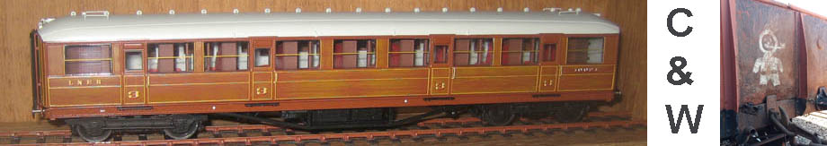
The dynamo and battery are carried under the vehicle slung from
the underframe. On corridor stock the auto switch, regulator,
distance switch, through control switch and fuse board are housed
in a cupboard at one end of the corridor, whilst on non-corridor
stock they are in a box slung from the underframe. On brake
vehicles they are now installed in the guard's compartment.
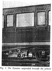
The Dynamo (Fig. 1).
The dynamo is suspended, pendulum fashion, from the
underframe of the vehicle by means of a pivoted hanger. It is driven by
a belt from a pulley on the inner axle of the adjacent bogie and the
length of the belt is so adjusted that it pulls the dynamo out of the
vertical through the pivot, so that the weight of the dynamo itself
tends to maintain the belt tension. This tension is further controlled
by a spring attached to the. pin through the suspension lug and to a
point on the underframe of the vehicle.
The dynamo itself is of the four pole, wave wound type with
shunt field. There are two distinct sets of field coils. One, the
main field, is connected to the positive main brush and to a third
brush set nominally half way between the main brushes. The other,
called the auxiliary field, is connected to the main positive and
negative brushes and is only energised when the lamps are on. The
brushes are mounted on rockers, one for the main brushes, and, to
allow for adjustment, a separate one for the third brush. When the
train reverses its direction, the friction of the brushes on the
commutator is sufficient to carry them through 180 electrical degrees,
so that their polarity remains the same. Without this provision,
upon reversal, the residual field magnetism would be in the wrong
direction, and the machine would fail to excite, and even if it would
excite, the polarity would be reversed and the current to the battery
would flow in the wrong direction. On open circuit the voltage
between the positive and third brushes should be practically half
that between the main brushes, the third brush being set exactly
half way between the other two. In practice, owing to small
variations in construction, this is often not realised, and furthermore
the voltage generated in one direction of rotation differs from that
in the other direction. It is for these reasons that provision is made
for adjusting the position of the third brush independently of the
main brushes.
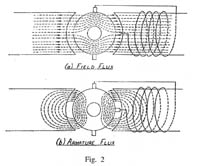 The voltage generated by a dynamo is proportional to the product
of the field strength and the speed of rotation. The speed of the
train lighting dynamo, excluding those systems where mechanical
provision is made to keep the speed constant above a certain
maximum train speed, varies with that of the train. Diagram (a), Fig. 2,
shows the lines of force of the field of a two-pole machine, this type
being used for purposes of illustration, although the actual machine
has four poles. Diagram (b) shows the field set up by the armature `
current. It will be seen that adjacent to the top right and bottom A at
left quadrants of the armature, the flux of the latter opposes that of
a the field, whilst in the other two quadrants it assists it. This is the
phenomenon known as armature reaction, and it increases as the
armature current increases. Now in the quadrant between the
positive main and the third brushes, to which the main field coils
are connected, the fluxes are in opposition. Therefore an increase
The voltage generated by a dynamo is proportional to the product
of the field strength and the speed of rotation. The speed of the
train lighting dynamo, excluding those systems where mechanical
provision is made to keep the speed constant above a certain
maximum train speed, varies with that of the train. Diagram (a), Fig. 2,
shows the lines of force of the field of a two-pole machine, this type
being used for purposes of illustration, although the actual machine
has four poles. Diagram (b) shows the field set up by the armature `
current. It will be seen that adjacent to the top right and bottom A at
left quadrants of the armature, the flux of the latter opposes that of
a the field, whilst in the other two quadrants it assists it. This is the
phenomenon known as armature reaction, and it increases as the
armature current increases. Now in the quadrant between the
positive main and the third brushes, to which the main field coils
are connected, the fluxes are in opposition. Therefore an increase
 in armature current results in a weakening of the flux responsible
for the generation of the third brush voltage and hence a decrease
of the field current. This in turn results in a weakening of the main
field flux which causes a decrease in the voltage across the main
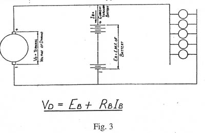
brushes. When the train starts, the dynamo is not connected to the
battery, and its voltage rises until it reaches about 27. At this
point the auto-switch closes and connects the dynamo to the battery.
Now considering the circuit through the dynamo and battery, we
have, by Kirchhoff's second law, (Fig. 3),
in armature current results in a weakening of the flux responsible
for the generation of the third brush voltage and hence a decrease
of the field current. This in turn results in a weakening of the main
field flux which causes a decrease in the voltage across the main
brushes. When the train starts, the dynamo is not connected to the
battery, and its voltage rises until it reaches about 27. At this
point the auto-switch closes and connects the dynamo to the battery.
Now considering the circuit through the dynamo and battery, we
have, by Kirchhoff's second law, (Fig. 3),
VD = EB + RBIB
whereVD = the terminal voltage of the dynamo
EB : the battery
RB : the resistance of the battery
IB = the current through the battery.
This would be true for any type of D.C. generator. RB is extremely
small but a normal dynamo would, as its speed increased, send a
very large current through the battery, so raising the value of the
product RBIB and enabling VD to exceed EB considerably, and
incidentally damaging itself and the battery. With the third brush
type of dynamo, however, the increase in IB which results from a
small increase in VD, involving, as it does, a corresponding increase V
in armature current, causes the flux between the main and third
brushes to be weakened. Thus the voltage across the main field
coils is reduced and consequently also the main field flux. A
reduction in main field flux means a reduction in terminal volts and in
battery current. It will therefore be seen that the value of the
product RBIB is limited and the terminal voltage of the dynamo
cannot materially exceed the voltage of the battery. It must not be
forgotten, however, that the voltage of the battery can vary from
about 22 when discharged to as much as 31.5 when on charge, the
charge being nearly complete. The terminal voltage of the dynamo
therefore also varies over a similar range. The regulating effect
cannot be satisfactorily obtained with a pure resistance load and
therefore it is essential that the battery be connected to the dynamo
at all speeds in excess of the cut-in speed. Otherwise the terminal
voltage would rise with speed, and eventually the field coils would
burn out. To guard against failure of the auto switch, a fuse is
included in the main field circuit, so that this would blow before the
field windings were damaged.
When the lamps are off, the main shunt field, connected to the
third brush, is alone in use, but, when lamps are switched on, a
greater current output is required, and so the operation of the
distance switch is arranged to bring the auxiliary field into use
automatically. The output of a third brush dynamo reaches a
maximum and then falls as the speed continues to rise, and the
auxiliary field helps to minimise this effect.
The series 7 dynamo, which is used for ordinary passenger stock,
is capable of an output of 70 amps at 27 volts, this output being
achieved at a speed of 800 r.p.m. The output at 600 r.p.m. is about
30 amps., whilst the variation at a speed of 2,000 r.p.m. is not to be
more than 25% of full load output. 70 amps is the maximum
output, the average over the speed range being about 55 amps.
In order to keep the battery in good condition and to avoid
excessive sulphation and distortion of the plates, it should receive
a relatively high charging current when discharged and this current
should gradually decrease when charging is nearing completion and
should be reduced to a very low value when the charge is complete.
 When, however, a battery is directly connected to a third brush
dynamo its charging current rises as the fully charged condition is
approached, because the voltage across the field coils rises, so
increasing the output of the dynamo. This of course is the opposite
of what is required. As previously explained, the terminal voltage
of the dynamo and battery can vary from 22 to over 30, but it is
desirable, for good illumination and long lamp life to keep the lamp
voltage as nearly constant as possible. Also the number of lamps in
circuit can vary from about ll to about 38, as the passengers switch
them on and off, and this variation in load must not be allowed to
cause excessive fluctuations in lamp voltage.
When, however, a battery is directly connected to a third brush
dynamo its charging current rises as the fully charged condition is
approached, because the voltage across the field coils rises, so
increasing the output of the dynamo. This of course is the opposite
of what is required. As previously explained, the terminal voltage
of the dynamo and battery can vary from 22 to over 30, but it is
desirable, for good illumination and long lamp life to keep the lamp
voltage as nearly constant as possible. Also the number of lamps in
circuit can vary from about ll to about 38, as the passengers switch
them on and off, and this variation in load must not be allowed to
cause excessive fluctuations in lamp voltage.
It is in order to achieve these desirable conditions that the
regulator is used.
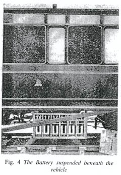
The Battery (Fig. 4).
The battery of the series 7 equipment consists of 12 lead acid cells
connected in series. Each cell comprises 8 positive and 9 negative
plates supported on teak rests in a glass box. The teak rests provide
space in the bottom where sediment can collect without interfering
with the plates. A teak lid is provided and the positive and negative
lugs pass through rubber gaskets in this lid. The positive plates are
of the Plante type and the negatives are of box construction. Wood
separators are used between the plates and the lids, rests and separ-
ators are wax impregnated.
The battery is carried in two timber boxes slung from the
underframe of the vehicle, each box containing six cells. The capacity of
the battery is 240 ampere hours at a 9-hour rate of discharge.
The Auto-Switch (Fig. 5).
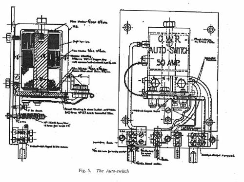
The auto-switch is mounted on a mild steel base. A U-shaped
mild steel magnet frame carries a soft iron core on which are the
series coil consisting of relatively few turns of insulated copper strip
and the shunt coil consisting of many turns of enamelled wire. A
pivoted armature is arranged to be attracted by the core and magnet
frame when the shunt coil is energised, and the movement of the
armature closes two contacts. One of these actually consists of two
brushes, and when these impinge on their fixed contact they connect
the dynamo positive to the battery positive. The other brush
impinges on a separate contact and provides a negative feed to a
component of the regulator called the voltage balance coil, this feed
being for use when the lamps are off and the battery is on charge.
The shunt coil is permanently connected across the positive and
negative of the dynamo and that is why it consists of a large number
of turns of fine wire, so that it only takes a small current. As soon
as the dynamo generates 27 volts, the pull of the shunt coil is
sufficient to attract the armature and close the contacts. Almost the
whole output of the dynamo then flows through the series coil,
which is the reason it consists of a small number of turns of large
section strip so that it can carry a heavy current, and the pull of this
coil then assists that of the shunt coil and improves the contact
pressure.
When the train slows down, the dynamo voltage falls below that
of the battery and there is a small reverse flow of current through
the series coil, which sufficiently weakens the pull of the shunt coil
to cause the switch to open, disconnecting the dynamo from the
battery.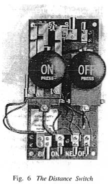
The Distance Switch (Fig. 6).
Like the auto-switch, the distance switch is mounted on a mild
steel base. Each of two channel section magnet frames has a core
carrying a coil, the left hand being the pull-on coil and the right
hand the pull-off coil. A pivoted armature on the "on" side carries
three contact brushes. One of these is in the lamp circuit, one
provides the positive feed to the voltage balance coil of the regulator
when the lamps are on, and the third provides the negative feed to
this coil, likewise when the lamps are on. This armature is attracted
when its coil is energised by operation of a through control switch
anywhere on the train, or it can be pushed home by hand, a knob
labelled "on" being fitted for this purpose. When contact, is made
a spring controlled trigger engages with a pin on the armature and
holds the switch in the "on" position. The pull-off coil is equipped
with a similar pivoted armature, but this one has no contacts.
I Instead, its function is to press against a lever attached to the
trigger and so release the "on" armature. This armature also can
be pushed in by hand and is provided with a knob labelled "off."
The Regulator (Fig. 7).
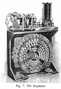 The regulator consists of a stout rectangular cast iron frame on
which are mounted, concentrically, three resistances known
respectively as the lamp resistance, the progressive resistance and the shunt
resistance. They consist of short coils of Eureka wire, those for the
progressive resistance being wound on small bobbins. In front is a
circular plate of insulating material called the rheostat base. The
resistances are fixed to the base with brass studs, the heads of which
form contacts for the contact arm. This contact arm, a brass casting,
carries six spring loaded carbon brushes which bear on the resistance
studs and on two contact rings mounted on the rheostat base. At
each end of each row of contact studs is a brass end plate. The
contact arm is carried on, but insulated from, a steel spindle which
is driven through double worm reduction gearing by a small series
wound reversing motor, mounted on top of the frame. The motor
has two sets of field coils, one being energised for one direction of
rotation and the other being energised for the other direction. The
motor exerts sufficient torque to operate the contact arm over the
full range of battery voltage.
The regulator consists of a stout rectangular cast iron frame on
which are mounted, concentrically, three resistances known
respectively as the lamp resistance, the progressive resistance and the shunt
resistance. They consist of short coils of Eureka wire, those for the
progressive resistance being wound on small bobbins. In front is a
circular plate of insulating material called the rheostat base. The
resistances are fixed to the base with brass studs, the heads of which
form contacts for the contact arm. This contact arm, a brass casting,
carries six spring loaded carbon brushes which bear on the resistance
studs and on two contact rings mounted on the rheostat base. At
each end of each row of contact studs is a brass end plate. The
contact arm is carried on, but insulated from, a steel spindle which
is driven through double worm reduction gearing by a small series
wound reversing motor, mounted on top of the frame. The motor
has two sets of field coils, one being energised for one direction of
rotation and the other being energised for the other direction. The
motor exerts sufficient torque to operate the contact arm over the
full range of battery voltage.
Also mounted on top of the frame are two motor operating
relays, one for each direction and the voltage balance. The voltage
balance consists of a pivoted arm at each end of which is an
adjustable contact point arranged over a cup containing a small quantity
of mercury. One end of the arm is attached to a tension spring and
the other is attached to the plunger of a solenoid, the coil of which
is called the voltage balance coil. When the voltage across this coil
is 22, the pull of the plunger balances the pull of the spring, and
both points are held clear of the mercury in the cups. When the
voltage drops below 22, the spring pulls its end of the arm
downwards, the point dips into the mercury and completes the circuit to
the coil of one of the motor operating relays. The switch closes and
the motor starts, revolving the arm until the voltage across the
balance coil is again 22. When the voltage rises above 22 the solenoid
pull exceeds that of the spring and the other relay is energised so that
the motor starts in the opposite direction. When the arm revolves
in a clockwise direction it inserts some of the shunt resistance and
some of the lamp resistance or the progressive resistance, according
to whether the lamps are on or not. This point will be explained
more fully later. When the arm revolves in an anti-clockwise
direction it cuts resistance out of circuit. The shunt resistance is in
series with the main field coils of the dynamo.
At each end of the travel of the contact arm is a simple
self-resetting limit switch in the circuit of the appropriate field coil of
the motor. When the arm reaches the limit of its travel it makes
contact with the arm of the limit switch, opens the switch, and the
motor stops. This of course does not prevent the other coil from
being energised when there is need for the arm to move in the
opposite direction, and when this happens, the limit switch closes
again.
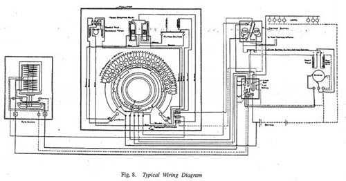 At the bottom of the rheostat base are five terminals numbered
from left to right 6, 8, 7, 5 and 8a (Fig. 8). 6 is connected internally
to the left hand end plate of the lamp resistance and externally to
the positive of the battery. 8 is connected internally to the lamp
resistance via the inner contact ring and the contact arm, and
externally to the lamps via the distance switch. The two lamp
resistance terminals are therefore 6 and 8. 7 is connected internally
to the right hand end plate of the shunt resistance and externally to
the main shunt coil of the dynamo. 5 is connected internally to the
outer contact ring and externally to the positive of the dynamo. The
two terminals for shunt resistance are therefore 5 and 7. 8a is
connected internally to the left hand end plate of the progressive
resistance and externally to the positive end of the voltage balance
coil. The contact arm connects the progressive resistance to the
outer contact ring and so via 5 to the positive of the dynamo. The
progressive resistance is thus in series with the voltage balance coil.
At the bottom of the rheostat base are five terminals numbered
from left to right 6, 8, 7, 5 and 8a (Fig. 8). 6 is connected internally
to the left hand end plate of the lamp resistance and externally to
the positive of the battery. 8 is connected internally to the lamp
resistance via the inner contact ring and the contact arm, and
externally to the lamps via the distance switch. The two lamp
resistance terminals are therefore 6 and 8. 7 is connected internally
to the right hand end plate of the shunt resistance and externally to
the main shunt coil of the dynamo. 5 is connected internally to the
outer contact ring and externally to the positive of the dynamo. The
two terminals for shunt resistance are therefore 5 and 7. 8a is
connected internally to the left hand end plate of the progressive
resistance and externally to the positive end of the voltage balance
coil. The contact arm connects the progressive resistance to the
outer contact ring and so via 5 to the positive of the dynamo. The
progressive resistance is thus in series with the voltage balance coil.
 The Function of the Regulator.
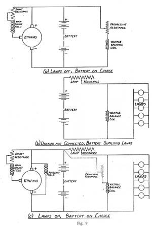
In order to understand the functioning of the regulator it is
helpful to consider the following three conditions: (Fig. 9).
- (l) Dynamo connected, lamps off, battery on charge.
- (2) Dynamo not connected, battery supplying lamps.
- (3) Dynamo connected, lamps on, battery on charge.
Condition (1). Under this condition the whole of the output of the dynamo is employed in charging the battery. As soon as the dynamo voltage reaches a value of 27 volts, the current through the shunt coil of the auto-switch causes the latter to close, connecting the dynamo to the battery via the series coil. The full output current of the dynamo then flows through the series coil and as previously explained, strengthens the action of the shunt coil ensuring firm pressure between the contacts. When the distance switch is open, that is when the lamps are off, the auxiliary contact 4 is open and the positive feed to the voltage balance coil is via the progressive resistance. That is to say the voltage balance coil and the progressive resistance are in series and are together in parallel with the battery, as shown in 9a.
Assuming that the battery is in a discharged condition, minimum
resistance will be required in series with the voltage balance coil so
that the voltage across the latter may be at the requisite value of
22, enabling it to balance the pull of the spring and maintain
equilibrium. The regulator contact arm will therefore be well over to
the left and there will be no resistance in series with the shunt held.
The dynamo output and the battery charging current will be high.
As charging proceeds, the battery voltage rises, the dynamo
voltage rises with it, and consequently the voltage across the voltage
balance coil increases. The pull of the latter overcomes the spring,
contact is made with the right hand cup, and the left hand motor
operating relay closes. The left hand field coil of the reversing motor
is energised and the motor drives the arm in a clockwise direction,
inserting progressive resistance in series with the voltage balance
coil, until the pull of the latter is just sufficient once more to balance
the pull of the spring and hold both contacts clear of the cups so
stopping the motor. Owing to the length of the end plate of the
shunt resistance the movement of the arm has not as yet inserted
any resistance in series with the field. The rising battery voltage
causes the voltage across the voltage balance coil to tend constantly
to rise with the further insertion of progressive resistance as above
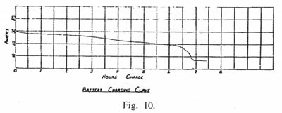
described. Eventually the contact arm brush controlling the shunt
resistance leaves the long end plate and begins to insert resistance
in the shunt field circuit. This causes the excitation and hence the
output of the dynamo to fall and the battery charging current
gradually decreases giving a tapering charge characteristic.
Eventually the brush controlling the progressive resistance makes contact
with the right hand end plate from which there is a back connection
to the third stud. The effect of this is to cut out the greater part of
the progressive resistance so that the voltage across the voltage
balance coil rises, the arm travels right over, inserting all the shunt
resistance, until it strikes the right hand limit switch, cuts out the
motor, and remains in that position. With all the shunt resistance
inserted, the dynamo output is greatly reduced, and by this time the
battery is fully charged. The charge then continues at a rate sufficiently
low to prevent damage to the plates. (Fig. 10).
 In the event of the battery voltage exceeding that of the dynamo,
as will happen if the train slows down, the current in the series coil
of the auto-switch is momentarily reversed and causes the
auto-switch to open, disconnecting the battery from the dynamo.
In the event of the battery voltage exceeding that of the dynamo,
as will happen if the train slows down, the current in the series coil
of the auto-switch is momentarily reversed and causes the
auto-switch to open, disconnecting the battery from the dynamo.
Condition (2). Under this condition the essential connections are
as shown in 9b. Current flows from the positive of the battery via
the end plate or the studs of the lamp resistance to the lamps and
back to the negative of the battery. The voltage balance coil is in
parallel with the lamps but the progressive resistance is not now in
circuit since it can only receive a positive feed from the dynamo,
which is not connected. The contact 4 on the distance switch now
provides the negative feed to the voltage balance coil, in place of
the contact 4 on the auto-switch.
The voltage of the battery can vary from about 22 to nearly 30
according to the state of charge. The working voltage of the lamps
is 22. Therefore whenever the battery voltage exceeds 22 it is
necessary to insert resistance in series with the lamps to absorb the
difference. This is the lamp resistance. Now the voltage balance
coil is in parallel with the lamps and therefore the voltage across it
is the same as that across the lamps, and as previously explained
whenever this voltage varies from 22 the voltage balance operates
to drive the contact arm in the appropriate direction to re-establish
the value at 22. Under the conditions now being considered this
results in the addition or subtraction of lamp resistance. As current
is taken from the battery, it is gradually discharged and its voltage
falls, the voltage across the voltage balance coil and the lamps falls .
below 22 and the contact arm moves anti-clockwise to subtract
lamp resistance to re-establish the correct lamp voltage.
Now there are some 38 lamps in a coach, most of which can be
switched on and off by the passengers. Suppose that only a few of
the lamps are on and suficient lamp resistance is in circuit to
maintain the lamp voltage at 22. The voltage drop in the lamp resistance,
equal to the difference between 22 and the battery voltage, is equal
to IR, where R is the value of the lamp resistance in circuit and I is
the value of the current in it. If now more lamps are switched on,
the current in the circuit and therefore through the lamp resistance
increases. Consequently the value of IR, the drop in the lamp
resistance increases, so that the voltage across the voltage balance
coil and the lamps falls below 22. The balance then operates to
move the contact arm anti-clockwise to subtract resistance until the
lamp voltage is again 22. If lamps are switched off, the reverse takes
place.
Condition (3).
The lamps will be fed from the battery as just
described if the train is stationary, or is moving at a speed less than
that at which the auto-switch cuts in. lf the speed of the train
increases so that the dynamo generates a voltage of 27 the current
in the shunt coil of the auto-switch is sufficient to close the
auto-switch as previously described, and then the conditions shown
in 9c obtain. Current now flows through the battery in the reverse
direction, from the dynamo, and the battery is on charge. Its voltage
begins to rise and tends to increase the voltage across the lamps and
the voltage balance coil, and the voltage balance acts to insert more
lamp resistance and at the same time more shunt resistance, so that
the charging current to the battery is controlled in a similar manner
to that already described for the condition "Lamps off, battery on
charge". It will be noted however that the control is now exercised _
by the lamp resistance instead of the progressive resistance.* Switching
individual lamps on and off produces the same results as described
for the condition "Dynamo not connected, battery supplying lamps".
If more lamps are switched on lamp resistance is cut out and also of
course shunt resistance, but while this increases the output of the
dynamo, it does not materially affect the charging current, because
the extra output is required for the extra lamps. Similarly when
lamps are switched off the dynamo output is reduced and this
compensates for the lower lamp consumption, and prevents the
charging current from increasing.
When the train slows down again the auto-switch will disconnect
the dynamo as previously described, and the regulator will subtract
lamp resistance to compensate for the fact that the battery voltage is
lower on discharge than on charge.
Conclusion.
It is hoped that the foregoing has given a clear impression of the
principles of the train lighting system at present in use on British
Railways, Western Region. The description has been confined to
the equipment of ordinary passenger stock. Another paper would
probably be needed to describe the equipment in more detail and
also the additional items used on various other types of vehicles.
Fans, refrigerators, electric food warmers and fluorescent lamps are
all operated from what is basically the same power plant, though
various modifications are made to cope with the differing
requirements. Probably the most fundamental alterations and additions
are made for the fluorescent lamps.
At the present time it is difficult to say how long the system will
remain in use but, developed in close co-operation with Great
Western engineers, it has for many years efficiently performed its
functions. Finally, it may be said that although the various systems
in use differ widely in detail, an understanding of the basic principles
of the Western Region system will be very helpful in understanding
other systems.
* In point of fact, the progressive resistance is now in parallel with the lamp resistance, as shown dotted in the diagram, but since its resistance is so much greater than that of the lamp resistance its effect is small.