
This is the first half decent circuit diagram of the Wolverton MD Regulator I have seen. The operation of the regulator is described (at some length) in the Wolverton Patent. Any handbook or user/maintenance guide on the regulator seems to use the Patent text verbatim. Robin Nelson, a stalwart at Bo'ness has rewritten the description of the regulator to make it rather more 'user' friendly.

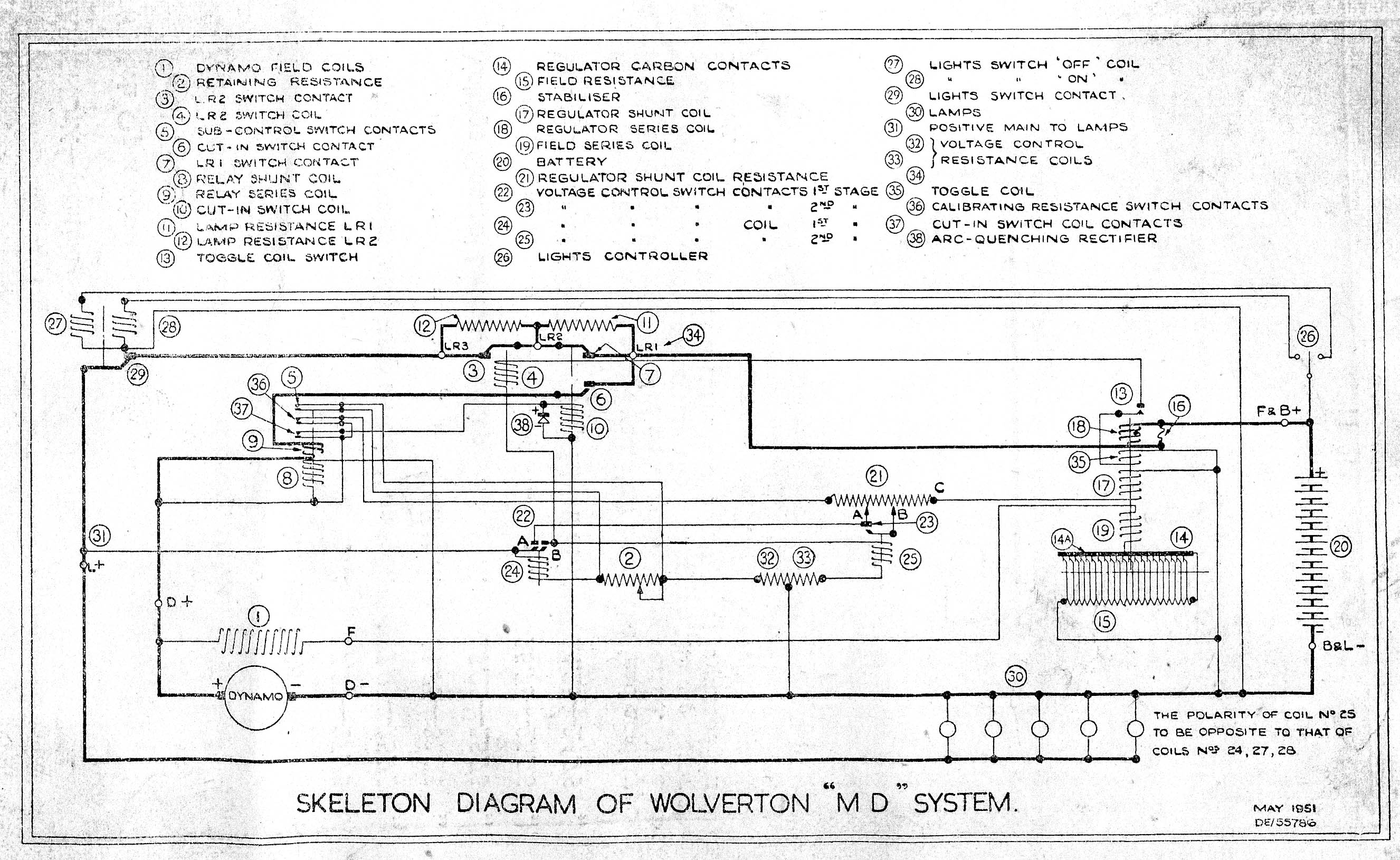
Robin found the diagram below in a BR handbook dated 1951. This diagram shows the more recent version of the MD regulator where a triple pole relay is used to sense the dynamo pull-in voltage. Because of the width of the page, this diagram is small and quite difficult to read. If you click here, you can see the same schematic but at a printable resolution of 300dpi.

As has been stated elsewhere on the website, but just to hammer home the point, there are two common variants of the Wolverton system. Normally used in TSO's, FO's, FK's and brakes is the MD regulator which is paired with a W or WA type dynamo. Where more power is required, for example in RMB's a CMD regulator is paired with a WC type dynamo. The W or WA dynamo is rated at 70A max whereas the WC dynamo is rated at 90 - 100A. The resistance of the field coils in the dynamos must be matched with the correct regulator as there is a 4:1 difference between the two systems. Don't match either type of dynamo with the wrong regulator or you will get TROUBLE!