Winter 2018/Spring 2019
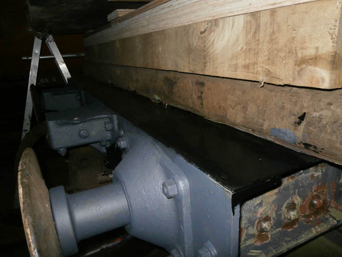
Several of the sites where the body supporting rubbers had rested on the solebar, due to the moisture retentive design, corrosion had occurred. As these sites were also the places where the body holding bolts were secured, it was felt necessary to first clean the area of scale and rust, then remove paint from underside of the area so welding could take place. Brian filled the pits with weld then ground the excess weld off to get a good thick piece of chassis back. The newly welded west end plate can be seen to the right of the picture.
After everything had turned green, the next job was to make everything chassis-wise turn to grey undercoat. This was applied
prior to the final coat of gloss black (within the chassis). The outer surface of the solebar was to be painted in LNER "teak" brown.
While applying the undercoat various "missed" patches were found in some of the extremely obscure corners so further "greening" was required. It was also felt that the needle
gunning of the west headstock was not good enough, so that was redone then painted.
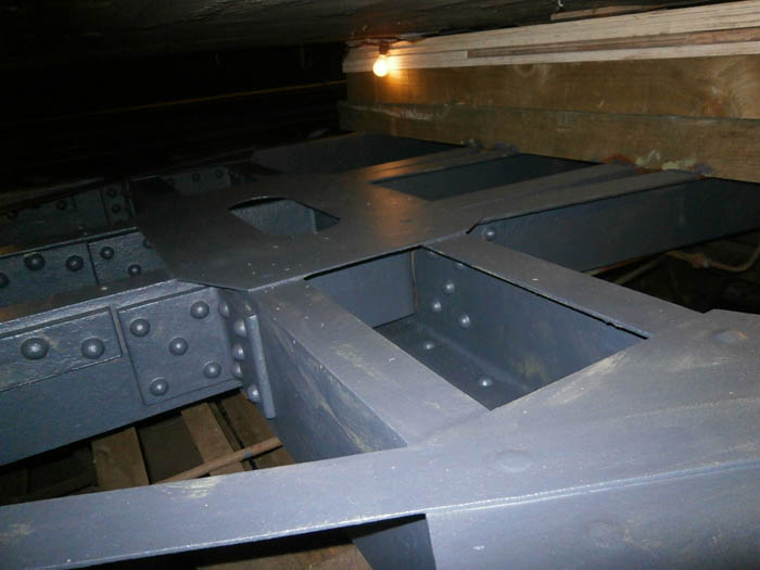
Brian Williams welded the east end plate later in the month. After welding it was undercoated in grey and then glossed in chassis black. The headstock is still in grey undercoat - eventually it is to be painted in LNER "teak" brown, the same colour as is to be used on the outer face of the solebar.
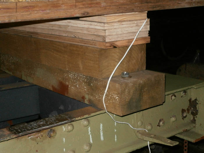
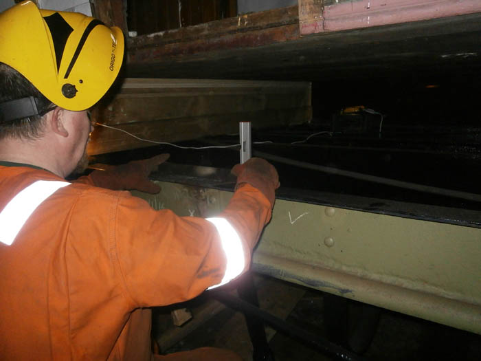
Filling in of the wasted areas of solebar took several weeks. Brian Williams had to weld in lots of fill, then sand back to horizontal as a flat surface to mate with the rubber spacers which support the wooden body. The photo below shows Brian checking that the fill is enough to bring the surface flat enough to support the rubber spacers.
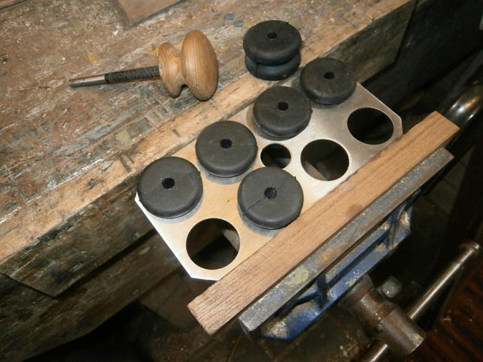
Once all the welding and painting was finished, Brian made sure all the steam heating tap-off points were freed on the main steam pipe. Then the lowering of the body began. The rubber bung support plates were placed along the top of the chassis members at which point it was discovered we didn't have the right number made up. So the "bung insertion" process was re-started - see below. As the body was lowered it became apparent that it was not perfectly aligned with the chassis. Brian experienced considerable difficulty when trying to skew it back into its original position.